بناء جسم الجهاز
المطلوب لتنفيذ هذا المشروع هو لوح من الخشب 3 ملم.
نقوم برسم الأجزاء المطلوبة على الألواح الخشبية وفقًا للرسومات باستخدام منشار صغير تقطع كل الأجزاء إلى الحجم و الشكل المطلوب ، كما موضح بالصورة التالية
بمجرد أن أصبحت جميع الأجزاء جاهزة ، نبدأ في تجميعها. أولا قمت بتجميع الأجزاء الخارجية بإستخدام مسدس الغراء.
ثم نستخدم الغراء مرة أخرى لتثبيت محركين المؤازرة servo motor كل موتور بقطعة الخشب الخاصة به و ربط قطعة خشب الدليل بالموتور السفل تجميعهم مع جسم الجهاز الكلى كما موضح بالصور .
بعد ذلك ، يتم إدخال مفتاحًا ومقبسًا كهربائيًا لتزويد دائرة الاوردينو Arduino بطاقة 5V و في المنصة الثالثة قم بإدخال جهاز استشعار الألوان .
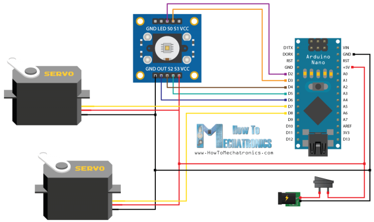
يتم توصيل المكونات الكهربائية طبقا لرسم الدائرة فى الصورة التالية
 |
| رسم دوائر كهربية مبسطة |
برمجة الاردينو Arduino Code
يجب الان ان نبدأ فى برمجة الاردينو قبل أن يتم تثبيت بوردة الاردينو فى جسم الجهاز ، و هذا هو البرنامج المستخدم لبرمجة الأردينو الخاص بالمشروع
/* Arduino Project - Color Sorting Machine
*
* by Dejan Nedelkovski, www.HowToMechatronics.com
*
*/
#include <Servo.h>
#define S0 2
#define S1 3
#define S2 4
#define S3 5
#define sensorOut 6
Servo topServo;
Servo bottomServo;
int frequency = 0;
int color=0;
void setup() {
pinMode(S0, OUTPUT);
pinMode(S1, OUTPUT);
pinMode(S2, OUTPUT);
pinMode(S3, OUTPUT);
pinMode(sensorOut, INPUT);
// Setting frequency-scaling to 20%
digitalWrite(S0, HIGH);
digitalWrite(S1, LOW);
topServo.attach(7);
bottomServo.attach(8);
Serial.begin(9600);
}
void loop() {
topServo.write(115);
delay(500);
for(int i = 115; i > 65; i--) {
topServo.write(i);
delay(2);
}
delay(500);
color = readColor();
delay(10);
switch (color) {
case 1:
bottomServo.write(50);
break;
case 2:
bottomServo.write(75);
break;
case 3:
bottomServo.write(100);
break;
case 4:
bottomServo.write(125);
break;
case 5:
bottomServo.write(150);
break;
case 6:
bottomServo.write(175);
break;
case 0:
break;
}
delay(300);
for(int i = 65; i > 29; i--) {
topServo.write(i);
delay(2);
}
delay(200);
for(int i = 29; i < 115; i++) {
topServo.write(i);
delay(2);
}
color=0;
}
// Custom Function - readColor()
int readColor() {
// Setting red filtered photodiodes to be read
digitalWrite(S2, LOW);
digitalWrite(S3, LOW);
// Reading the output frequency
frequency = pulseIn(sensorOut, LOW);
int R = frequency;
// Printing the value on the serial monitor
Serial.print("R= ");//printing name
Serial.print(frequency);//printing RED color frequency
Serial.print(" ");
delay(50);
// Setting Green filtered photodiodes to be read
digitalWrite(S2, HIGH);
digitalWrite(S3, HIGH);
// Reading the output frequency
frequency = pulseIn(sensorOut, LOW);
int G = frequency;
// Printing the value on the serial monitor
Serial.print("G= ");//printing name
Serial.print(frequency);//printing RED color frequency
Serial.print(" ");
delay(50);
// Setting Blue filtered photodiodes to be read
digitalWrite(S2, LOW);
digitalWrite(S3, HIGH);
// Reading the output frequency
frequency = pulseIn(sensorOut, LOW);
int B = frequency;
// Printing the value on the serial monitor
Serial.print("B= ");//printing name
Serial.print(frequency);//printing RED color frequency
Serial.println(" ");
delay(50);
if(R<45 & R>32 & G<65 & G>55){
color = 1; // Red
}
if(G<55 & G>43 & B<47 &B>35){
color = 2; // Orange
}
if(R<53 & R>40 & G<53 & G>40){
color = 3; // Green
}
if(R<38 & R>24 & G<44 & G>30){
color = 4; // Yellow
}
if(R<56 & R>46 & G<65 & G>55){
color = 5; // Brown
}
if (G<58 & G>45 & B<40 &B>26){
color = 6; // Blue
}
return color;
}
الأن نستطيع تثبيت لوحة الاردينو فى جسم الجهاز ثم نقوم بلزق الانبوب الشفاف الذى سيحتوى الدوائر الملونة
و هكذا يكون المشروع انتهى
اذا كان لديك اى استفسار عن المشروع يمكنك تركه فى تعليق :)
لدعم المدونة للإستمرار يمكنك شراء منتجات الاردوينو من موقع امازون من هذا الرابط
https://www.amazon.ae/gp/search/ref=as_li_qf_sp_sr_il_tl?ie=UTF8&tag=lakanata1-21&keywords=arduno&index=aps&camp=247&creative=1211&linkCode=xm2&linkId=9630bab8d96f5277f8462fce9b790396
يشرفنا و يسعدنا
إشتراكك فى قائمتنا